
Le module Heltec W8266
introduction
Dès fois le père noël passe en avance.
Cette année il m'a amené le module Heltec W8266.
Ce module a été commercialisé début Septembre 2017.
Alors que le passage sous Arduino Mega m’embêtait pour des questions de prix et d'encombrement, ce module résout tous ces inconvénients, tout en conservant les avantages de celui-ci.
Il ne nécessite quasiment aucune adaptation de mon code existant.
Fonctionnalités :
Wifi par ESP8266 programmable en arduino en NodeCMU
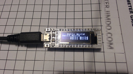
Ecran Oled 128*32 de 91 pouces, 4 lignes de 13 caracteres
Alimentation par Micro USB ou batterie externe
32Mo de mémoire
12 pins tous configurables en input/output, 1 port I2c, 1 port Spi, support du PMW...
Working voltage: 3.3V ~ 7V
Dimension : 600*200 mm
Prix : 8 euros
ESP Kit HTIT series manual (example code include) download link : https://pan.baidu.com/s/1kVuZHdl
WIFI Kit 8
Inconvénient :
Il n'y a pas assez de ports disponibles pour le smartboard.
Remarque :
Attention a ne pas le confondre avec le modèle Lora.
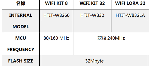
Heltec propose actuellement 3 cartes :
WIFI_Kit_8(HIIT-8266),
WIFI_Kit_32(HIIT-WB32),
WIFI_LoRa_32(HIIT-WB32LA)

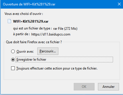
Téléchargement
Parce que tout est en chinois et qu'on peut récupérer des trucs bizarres, ci dessous la procédure de téléchargement des exemples
http://pan.baidu.com/s/1kVuZHdl


Config de l'Ide
Download:
Http://pan.baidu.com/s/1dFcmSZf
Password: li7
After downloading and decompressing, copy the "heltec" folder to the \arduino\hardware folder.
Each board has done at least two basic functional tests before
"program download test",
"WIFI scan test",
"OLED screen dead pixels and display test",
"charge and discharge function test" ,
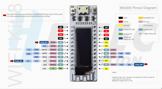
Schema
Le schéma des pins :
| static const uint8_t SDA = 2; | |
| static const uint8_t SCL = 14; | |
| static const uint8_t D0 = 16; | |
| static const uint8_t D1 = 5; | |
| static const uint8_t D2 = 4; | |
| static const uint8_t D3 = 0; | |
| static const uint8_t D6 = 12; | |
| static const uint8_t D7 = 13; | |
| static const uint8_t D8 = 15; | |
| static const uint8_t RX = 3; | |
|
static const uint8_t TX = 1;
SDA=4 -> occupé par Oled SCL=5 -> utilisé par Oled MISO=12 MOSI=13 SCK=14 |
Setting Up the Arduino IDE for the ESP8266 Range
The ESP8266 boards are much easier to set up in the Arduino IDE than the ESP32 range. If you don’t already have it installed, download and install the IDE from here: https://www.arduino.cc/en/main/software (don’t use the Web version).
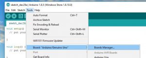
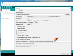
In the IDE, open the File Menu and choose Preferences and enter http://arduino.esp8266.com/stable/package_esp8266com_index.json into the Additional Board Manager URLs field.
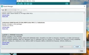
Open the Boards Manager from Tools > Board:xxxxx menu
Find esp8266 by ESP8266 Community in the list and click Install
The ESP8266 Hardware Libraries are now installed and you can test your new board with a simple Sketch.
Testing the WiFi is Functioning
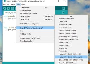
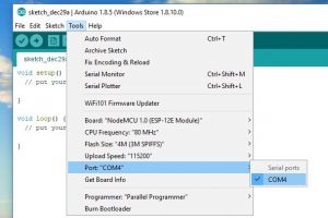
In the Arduino IDE, in the Tools > Board menu choose NodeMCU 1.0 (ESP-12E Module)
Select the port (It might not be COM4)
You can now upload Sketches to the board. A good test is use the example WiFiScan sketch.
Open File> Examples > ESP8266WiFi > WifiScan and upload the sketch.
If you open the Serial Monitor (Tools > Serial Monitor) you will be able to see any WiFi access points in range. Check the baud rate is the same as in the sketch – probably 115200.
Conclusions
Pas assez de memoire si je veux conserver la trame et des messages en local.
Par contre, a tester avec 2 lecteurs RDM6300 et 2 lecteurs MFRC522, si la solution retenue utilise une seule de ces technologies.