
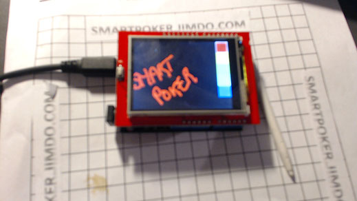
LCD module TFT 2.4 "
introduction
Encore un matériel hors sujet ?
Initialement je me suis dit que la SMARTCONSOLE pouvait etre un PC, un raspeberry, un orange Pi ou un arduino.
Le principe de cet ecran est de rendre l'arduino autonome pour la SMARTCONSOLE....en plus de m'amuser.
Ce qui est sur, c'est qu'il n'est pas PLUG and PLAY, avec 3 librairies à ajuster.
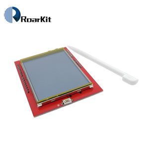
On peut donc ajouter à notre projet un écran tactile avec une carte microSD. cette TFT écran est grand (2.4 " diagonale) lumineux (4 blanc-LED rétro-éclairage) et coloré (18-bit 262,000 différentes nuances)! 240x320 pixels avec pixel individuel contrôle. il a beaucoup plus de résolution que un noir et blanc 128x64 affichage. comme un bonus, cet écran a un écran tactile résistif .Vous pouvez donc détecter une pression n'importe où sur l'écran.
caractéristiques :
Prix :
4,50 euros
Librairies :
Il faut charger au moins 3 librairies en fonctions des besoins
Affichage
LCD pilote est Ili9341. fonctionne avec tous les SPDF5408
https://github.com/JoaoLopesF/SPFD5408
TouchScreen :
Library needed for the touch, needs to be downloaded and moved to the folder that includes your Arduino libraries.... Rename the folder that is in ZIP file to "TouchScreen":
https://github.com/adafruit/Touch-Screen-Library
CarteSd :
datasheet :
Liste des erreurs connues :
Avec la librairie : https://github.com/JoaoLopesF/SPFD5408
When we try to use the TFT 2.4 with SPFD5408 controller in sketches with Adafruit TFT libraries, several things can happen :
- White Screen
- All screen with noise
- Touch not works or is inverted (coordinate Y)
- The colors are inverted
- And other things
Due to variations in Chinese shields with some controller, there is no guarantee that will work for everyone
please verify it:
—- Pinout XM XP, must be:
#define YP A1  // must be an analog pin, use "An" notation!
#define XM A2  // must be an analog pin, use "An" notation!
#define YM 7   // can be a digital pin
#define XP 6   // can be a digital pin

(please verify it, if only a blank screen or noise is showed or touch doesnt works)
—- readID: comment the original blok:
//  uint16_t identifier = tft.readID();
//
//  if(identifier == 0x9325) {
//    Serial.println(F("Found ILI9325 LCD driver"));
//  } else if(identifier == 0x9328) {
//    Serial.println(F("Found ILI9328 LCD driver"));
//  } else if(identifier == 0x7575) {
//    Serial.println(F("Found HX8347G LCD driver"));
//  } else if(identifier == 0x9341) {
//    Serial.println(F("Found ILI9341 LCD driver"));
//  } else if(identifier == 0x8357) {
//    Serial.println(F("Found HX8357D LCD driver"));
//  } else {
//    Serial.print(F("Unknown LCD driver chip: "));
//    Serial.println(identifier, HEX);
//    Serial.println(F("If using the Adafruit 2.8\" TFT Arduino shield, the line:"));
//    Serial.println(F("  #define USE_ADAFRUIT_SHIELD_PINOUT"));
//    Serial.println(F("should appear in the library header (Adafruit_TFT.h)."));
//    Serial.println(F("If using the breakout board, it should NOT be #defined!"));
//    Serial.println(F("Also if using the breakout, double-check that all wiring"));
//    Serial.println(F("matches the tutorial."));
//    return;
//  }
//
//  tft.begin(identifier);
—- tft.begin: insert after block commented
tft.begin(0x9341); // SDFP5408
—- tft.rotation: Need for Mega (else screen is showed mirrored)
tft.setRotation(0); // Need for the Mega, please changed for your choice of rotation initial
—- Calibrate before run
Exists one sketch written for my, to help in calibration of touch
See it in examples folder
Run it and change this parameters:

#define TS_MINX 150
#define TS_MINY 120
#define TS_MAXX 920
#define TS_MAXY 940

(please verify it if the point of touch is not accurate)
————————
All changes in Adafruit code is marked with:
// ### SPFD5408 change -- Begin
(change)
// ### SPFD5408 change -- End
This is useful if You see the points that be workeds for any touble
——————
Code couleurs
Le format de codage des couleurs est : RGB565
il est similaire au RGB888, mais n'utilisent que 16 bits (5+6+6) au lieu de 24 (8++8+8) pour les teintes RGB.
Le site ci dessous permet de calculer les valeurs RGB565
http://www.barth-dev.de/online/rgb565-color-picker/
Après plusieurs heures de tests, 3 Librairies semblent fonctionner correctement.
- McuFriend
-RalphBacon
-SPFD5408 - TFT librairies
Les autres fonctionnent partiellement

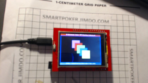
TESTS
tests raph Bacon Librairie
https://github.com/RalphBacon/TFT-LCD-Display-2.4-2.8-Touch-Shield
voir la vidéo dans la partie "démonstration"
test MCUFriends library
Code in this message should be added to MCUFRIEND_kbv.cpp file (it's in the library's folder): https://forum.arduino.cc/index.php?to... Correct place for that code is inside the "switch" that starts at line 820, in the begin-function. Copy pasting that code right after the line 820 should work.
Tous les exemples fonctionnent bien
test SPFD5408- TFT Library
Le code :
J'ai juste remplacé une couleur Magenta par Noir pour pouvoir gommer.

Afficher une image
On the SD card use 24 bit color BMP files (be sure they are 24-bit!)
MS Paint can be used to crop, resize and flip and save images in 24bit BMP format
Updated 31/3/15 to include new drawRAW() function that draws raw 16 bit images.
Raw images are created with UTFT library tool (libraries\UTFT_\Tools\ImageConverter565.exe)
Save as .raw file as this can be easily piped to the TFT pushColors() function without any tedious byte swapping etc
File names MUST use the 8.3 file name format (8 chars + . + any 3 extension letters)
By convention bitmap files end in .bmp
Bit maps MUST be in 24 bit colout (not 16 or 8 bit greyscale)
un conseil : Partir toujours d'une source au format jpg, cela semble plus stable dans les différents outils.
Afficher des boutons Excel Like
Introduction :
L'idée est d'avoir une palette de bouton standard.
Je souhaitais superposé des images issues des Box Excel
d'ou la section précédente.
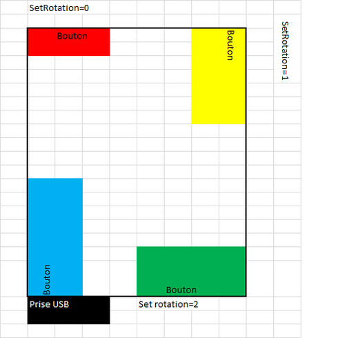
// the rotation change the localisation of the image
// Rotation =0, image in Min_x=25 Max_x=75 , Min_y=8, Max_x=75, Max_y=150
// Rotation=1 image in Min_x=250, max_x=300, Min_y=15,mac_y=75
// Rotation=2 image in Min_x=204, max_x=300, Min_y=230,mac_y=250
// Rotation=3 image in Min_x=8, max_x=75, Min_y=190,mac_y=250
// These values depends on the shape of the button
// to Determine theses values, use the debug mode and tap on the screen
// je dessine 4 traits pour creer un effet 3 D et je changerais la couleur pour l'effet
enfoncé
/* 0,0------------------BOX_W-10,0 (White or Black) ( 2ndtrait )
| 1,1-------------BOX_W-11 (gris clair ou gris foncé)
(3nd trait)
| |
| |
| |
| 1,BOX_H-11 (3eme trait)
0,BOX_H-10 (1er trait)
*/
En fonction de la valeur de tft.setRotation(), les coordonnées du bouton vont changer, il faudra donc rajouter une condition
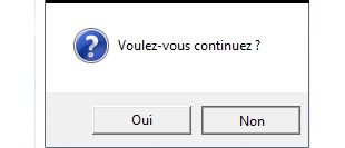
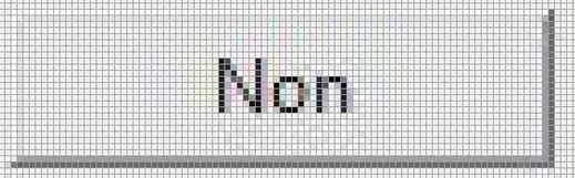
Creer un effet 3 D
Ces 2 copies sont extraits des messagebox d'excel
Dans le premier Cas , l'effet est produit par l'inversion de la couleur des rebords.
Dans le second cas, l'effet est produit par la bordure complete du bouton
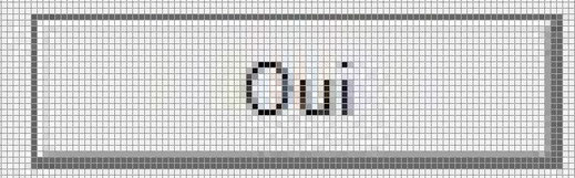
zoom sur la couleur :
Bouton Selectionné ->>>
Contour noir supplémentaire par rapport au bouton "Non selectionné"
-> Ne pas coller l'image au rebord
bouton non Selectionné ->>>>
Remplacement de la ligne noire par des lignes de la meme couleur que le fond
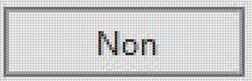
Bouton Appuyé ->>>>>>>>>>>
dans le cas d'un bouton de selection uniquement
les lignes blanches du bouton "Selectionnée" sont remplacées par des lignes grises foncées.
Conclusion :
L'effet visuel 3 D peut être crée par les 3 lignes extérieures d'un bouton.
Ceci permettra de dessiner ces propres boutons ultérieurement.
Le code :
Le code est indépendant de l'orientation de l’écran et de la taille de l'image correspondant au bouton


Une Montre
Une très belle montre.
Je n'en suis pas l'auteur, mais je n'ai plus le lien dans mes archives
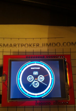
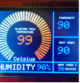
GAUGE
De très joli compteur aussi.
Par contre j'ai supprimé les appels aux sensors pour mettre des valeurs par defaut à 90.

L'ecran Blanc
L'ecran blanc est l'erreur la plus courante de ces ecrans.
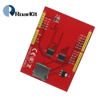
En fait, sous le meme packaging, vous pouvez avoir plusieurs puce et plusieurs cablages comme le montre les photos des 2 ecrans que j'ai acheté.
La solution consiste à afficher dans le moniteur Serie l'identifer
Pour les librairies suivantes :
#include <Adafruit_GFX.h> // Core graphics library
#include <Adafruit_TFTLCD.h> // Hardware-specific library
#include <TouchScreen.h>
il faut rajouter
tft.reset();
uint16_t identifier = tft.readID();
Serial.println ( tft.readID());
Si le code retour est C0C0,
Adafuit says that C0C0 mean bad communication with the module due to bad connections.
Sinon, il est recommandé de forcer l'initialisation en testant toutes les valeurs unitairements
/* A conserver pour debug si besoin
if(identifier == 0x9325) {
Serial.println(F("Found ILI9325 LCD driver"));
} else if(identifier == 0x4535) {
Serial.println(F("Found LGDP4535 LCD driver"));
}else if(identifier == 0x9328) {
Serial.println(F("Found ILI9328 LCD driver"));
} else if(identifier == 0x7575) {
Serial.println(F("Found HX8347G LCD driver"));
} else if(identifier == 0x9341) {
Serial.println(F("Found ILI9341 LCD driver"));
} else if(identifier == 0x8357) {
Serial.println(F("Found HX8357D LCD driver"));
} else {
Serial.print(F("Unknown LCD driver chip: "));
Serial.println(identifier, HEX);
//Serial.println(F("If using the Adafruit 2.4\" TFT Arduino shield, the line:"));
//Serial.println(F(" #define USE_ADAFRUIT_SHIELD_PINOUT"));
//Serial.println(F("should appear in the library header (Adafruit_TFT.h)."));
//Serial.println(F("If using the breakout board, it should NOT be #defined!"));
//Serial.println(F("Also if using the breakout, double-check that all wiring"));
//Serial.println(F("matches the tutorial."));
return;
}
*/
//tft.begin(identifier);
tft.begin(0x7575); //par exemple
Attention, meme si l'affichage fonctionne, la bibliotheque touchscreen risque d'etre KO, donc a tester en fonction de vos besoins.


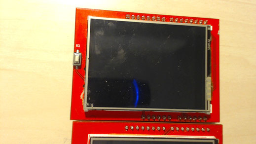

En facade, mise à part l'inscription sur l'ecran qui est trop petite a lire lors de l'achat, le cablage a partir du bouton de reset ( bouton blanc à gauche sur les photos) permet de distinguer ces 2 modeles.