
ESP12e et OLED 128*64
Le matériel
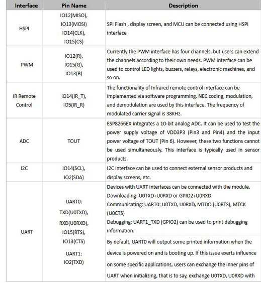
The Development Kit based on ESP8266, integates GPIO, PWM, IIC, 1-Wire and ADC all in one board.
Power your developement in the fastest way combinating with NodeMCU Firmware!
-
USB-TTL included, plug&play
-
10 GPIO, every GPIO can be PWM, I2C, 1-wire
-
FCC CERTIFIED WI-FI module(Coming soon)
-
PCB antenna
Attention : Le module ne délivre que du 3.3 v en sortie.
Les modules MFRC522 sont donc compatibles.
PROCESSEUR ! ESP8266MOD from AIThinker
lien
http://www.watterott.com/media/files_public/dthidgyib/AI-Thinker_ESP-12F.pdf
Prix : 3 à 4 euros
Matrice des pinouts
#define PIN_WIRE_SDA (4)
#define PIN_WIRE_SCL (5)
static const uint8_t SDA = PIN_WIRE_SDA;
static const uint8_t SCL = PIN_WIRE_SCL;
static const uint8_t LED_BUILTIN = 16;
static const uint8_t BUILTIN_LED = 16;
static const uint8_t D0   = 16;
static const uint8_t D1   = 5;
static const uint8_t D2   = 4;
static const uint8_t D3   = 0;
static const uint8_t D4   = 2;
static const uint8_t D5   = 14;
static const uint8_t D6   = 12;
static const uint8_t D7   = 13;
static const uint8_t D8   = 15;
static const uint8_t D9   = 3;
static const uint8_t D10 = 1;
Source :
http://www.instructables.com/id/WiFi-RFID-Reader/#comment-list
RST     = GPIO05 (free GPIO)
SS      = GPIO4  (free GPIO)
MOSI    = GPIO13 (HW SPI)
MISO    = GPIO12 (HW SPI)
SCK     = GPIO14 (HW SPI)
GND     = GND
3.3V    = 3.3V

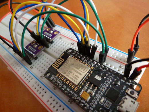
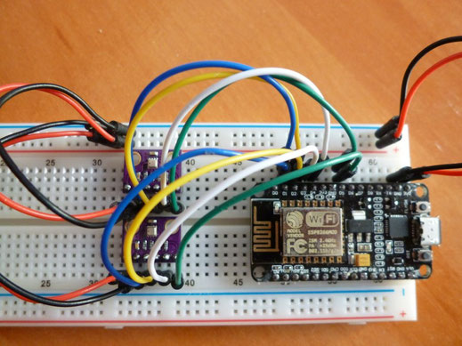
ESP12-e et OLED
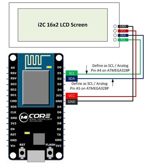
Cablage :
Ci contre
L'identification des pins I2C semble problématique.
Preparer l'IDE Arduino
Select the MENU option Tools → Board → Boards Manager…and scroll down and to locate the option esp8266 by ESP8266 Community which should be the last item on the list, and click INSTALL
- Installing The USB Drivers: The USB to Serial UART module included on the board is the Silicon Labs’ CP2012, for which we usually need to install the readily available Virtual COM Port (VCP) drivers. In the case of my MAC, the device file created to communicate with the CP2102 has the name/dev/cu.SLAB_USBtoUART. You can find the appropriate drive for your computer at following link: CP210x USB to UART Bridge VCP Drivers
- After restarting the Arduino IDE we can now select the board we’re using from the menu option Tools → Board → NodeMCU 1.0 (ESP-12E Module).Then, we specify the correct CPU Frequency (Tools → CPU Frequency: “” → 80MHz) and Upload Speed (Tools → Upload Speed: “” → 115200). Finally, the last step is to select the correct option for the Port (Tools → Port → /dev/cu.SLAB_USBtoUART).
la librairie Acrobotic
https://github.com/acrobotic/Ai_Ardulib_SSD1306
J'ai testé les librairies Adafruit et OLED des précédents articles, elles ne sont pas compatibles avec un ESP12E, d'ou une nouvelle librairie.
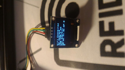
Premiers pas
Connexion Ip+oled
Code source :

Creer une image XMB
Source :
https://blog.squix.org/2015/05/esp8266-nodemcu-how-to-create-xbm.html
Fichier de l'image
Créer un fichier .h dans le répertoire de la librairie
exemple : image.h
#define WiFi_Logo_width 60
#define WiFi_Logo_height 36
const char WiFi_Logo_bits[] PROGMEM = {
0x00, 0x00, 0x00, 0x00, 0x00, 0x00, 0x00, 0x00, 0x00, 0x00, 0x00, 0xF8,
0x00, 0x00, 0x00, 0x00, 0x00, 0x00, 0x80, 0xFF, 0x07, 0x00, 0x00, 0x00,
0x00, 0x00, 0xE0, 0xFF, 0x1F, 0x00, 0x00, 0x00, 0x00, 0x00, 0xF8, 0xFF,
0x7F, 0x00, 0x00, 0x00, 0x00, 0x00, 0xFC, 0xFF, 0xFF, 0x00, 0x00, 0x00,
0x00, 0x00, 0xFE, 0xFF, 0xFF, 0x01, 0x00, 0x00, 0x00, 0x00, 0xFF, 0xFF,
0xFF, 0x03, 0x00, 0x00, 0x00, 0xFC, 0xFF, 0xFF, 0xFF, 0xFF, 0x00, 0x00,
0x00, 0xFF, 0xFF, 0xFF, 0x07, 0xC0, 0x83, 0x01, 0x80, 0xFF, 0xFF, 0xFF,
0x01, 0x00, 0x07, 0x00, 0xC0, 0xFF, 0xFF, 0xFF, 0x00, 0x00, 0x0C, 0x00,
0xC0, 0xFF, 0xFF, 0x7C, 0x00, 0x60, 0x0C, 0x00, 0xC0, 0x31, 0x46, 0x7C,
0xFC, 0x77, 0x08, 0x00, 0xE0, 0x23, 0xC6, 0x3C, 0xFC, 0x67, 0x18, 0x00,
0xE0, 0x23, 0xE4, 0x3F, 0x1C, 0x00, 0x18, 0x00, 0xE0, 0x23, 0x60, 0x3C,
0x1C, 0x70, 0x18, 0x00, 0xE0, 0x03, 0x60, 0x3C, 0x1C, 0x70, 0x18, 0x00,
0xE0, 0x07, 0x60, 0x3C, 0xFC, 0x73, 0x18, 0x00, 0xE0, 0x87, 0x70, 0x3C,
0xFC, 0x73, 0x18, 0x00, 0xE0, 0x87, 0x70, 0x3C, 0x1C, 0x70, 0x18, 0x00,
0xE0, 0x87, 0x70, 0x3C, 0x1C, 0x70, 0x18, 0x00, 0xE0, 0x8F, 0x71, 0x3C,
0x1C, 0x70, 0x18, 0x00, 0xC0, 0xFF, 0xFF, 0x3F, 0x00, 0x00, 0x08, 0x00,
0xC0, 0xFF, 0xFF, 0x1F, 0x00, 0x00, 0x0C, 0x00, 0x80, 0xFF, 0xFF, 0x1F,
0x00, 0x00, 0x06, 0x00, 0x80, 0xFF, 0xFF, 0x0F, 0x00, 0x00, 0x07, 0x00,
0x00, 0xFE, 0xFF, 0xFF, 0xFF, 0xFF, 0x01, 0x00, 0x00, 0xF8, 0xFF, 0xFF,
0xFF, 0x7F, 0x00, 0x00, 0x00, 0x00, 0xFE, 0xFF, 0xFF, 0x01, 0x00, 0x00,
0x00, 0x00, 0xFC, 0xFF, 0xFF, 0x00, 0x00, 0x00, 0x00, 0x00, 0xF8, 0xFF,
0x7F, 0x00, 0x00, 0x00, 0x00, 0x00, 0xE0, 0xFF, 0x1F, 0x00, 0x00, 0x00,
0x00, 0x00, 0x80, 0xFF, 0x07, 0x00, 0x00, 0x00, 0x00, 0x00, 0x00, 0xFC,
0x00, 0x00, 0x00, 0x00, 0x00, 0x00, 0x00, 0x00, 0x00, 0x00, 0x00, 0x00,
};
Appel dans le programme
ajouter dans le programme la ligne suivante
// Include custom images
#include "images.h"
Portage du logo Smartpoker
Le code doit etre rajouter dans le fichier image.h, et non dans un nouveau fichier.h
ou bien directement dans le programme
Exemple de 2 modules SPI
Source : https://robotzero.one/esp8266-two-bme280-sensors-spi/
Extrait du code source :
#include <Wire.h>
#include <SPI.h>
#include <Adafruit_Sensor.h>
#include <Adafruit_BME280.h>

// assign the ESP8266 pins to arduino pins
#define D1 5
#define D2 4
#define D3 0
#define D4 2
#define D5 14

// assign the SPI bus to pins
#define BME_SCK D1
#define BME_MISO D5
#define BME_MOSI D2
#define BME1_CS D3
#define BME2_CS D4

#define SEALEVELPRESSURE_HPA (1013.25)

Adafruit_BME280 bme1(BME1_CS, BME_MOSI, BME_MISO,
BME_SCK); // software SPI
Adafruit_BME280 bme2(BME2_CS, BME_MOSI, BME_MISO,
BME_SCK); // software SPI

ABANDON
Le module ne se comporte pas comme je l'attends.
Une fois le premier module RFID connecté, j'ai une sorte de conflit qui éteint soit l'ecran, soit le module.
apres lecture des docs et forum, certains pins ne doivent pas être utilisé comme GPIO0,GPIO02 et GPIO15 qui vont définir le mode de fonctionnement du module ( Mode Flash-Execution ou Mode UART-telechargement).
En plus je n'arrive pas a comprendre comment l'ecran I2C fonctionne sur des ports différents I2C de la doc et ne fonctionne pas sur les ports I2C de la doc.
Je suis descendu au niveau du module ESP8266MOD et AIThinker, mais je n'ai rien trouvé non plus.
A noter, ce module est aussi utiliser pour les ESP12-F
J'ai fait plusieurs tests de cablages entre les modules, sans succés
Mon niveau et materiel ne me permet pas de poursuivre avec ce module.
ce que je trouve bizarre sur le site de jorgen, c'est sa déclaration des ports RFID
http://www.instructables.com/id/WiFi-RFID-Reader/#comment-list
#include "MFRC522.h"
#define RST_PIN 15 // RST-PIN for RC522 - RFID - SPI - Modul GPIO15
#define SS_PIN  2  // SDA-PIN for RC522 - RFID - SPI - Modul GPIO2
MFRC522 mfrc522(SS_PIN, RST_PIN);   // Create MFRC522 instance
Le pin 15 n'est pas défini dans le schéma des pinouts.